
how to draw gear in autocad 2d
How do you draw a 2D shaft in AutoCAD. Measure the centre of the driven gear from the centre of the driver gear.
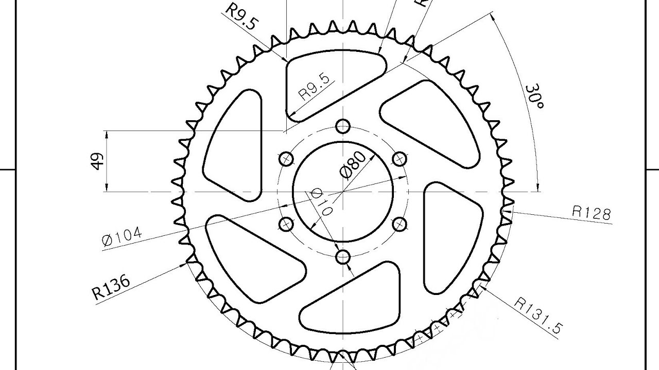
How To Make 2d For Gear In Autocad Grabcad Tutorials
Here is the Dimensions.
. Specify the starting radius of your spiral in Autocad. Learn from thousands of free tutorials join the community. 2D drawing is a drawing that sits in only the X and Y axis.
A second option would be to use a custom lisp routine that draws 2D gears input the required data let the routine draw the complete gear take what you need and erase the remainder. Autocad 2d mechanical practice drawings pdf. One way is to get yourself a book that explains the process or look it up on line.
Mar 21 2013 - Hi this is my 4th month at Westech School of technology. The user can modify it which can change the external diameter. It is a model design that helps one to Practice 2D Commands Easily.
Works on the Autodesk AutoCAD platform. In the drawing area select the objects that form the shaft to analyze. AutoCAD AutoCAD Architecture Compass Inventor Revit 3ds Max.
AutoCAD Telugu Tutorials Part -10 Practice Diagrams AutoCAD Telugu Tutorials Part -11 Practice Diagrams. Open up your CAD program and draw concentric circles of the Pitch Diameter D Base Circle diameter DB Outside Diameter DO and Root Diameter DR. CAD lessons CAD CAE CAM.
To draw spirals in Autocad click on the Draw pop-up menu as shown by the red arrow above. 02618 If anyone can help that will be. Measure the centre of the driven gear from the centre of the driver gear.
This method of drawing provides a fast way to create an isometric view of a simple design. Calculate the pitch centre distance. Gear Generator How to Draw Perfect Gears 423 Laser Cut Gears 308 Prototype your gear sets in 2D 119 Check out other tools I made.
Calculate the pitch centre distance. Today we will discuss one of the 2d commands and learn how to add patterns on a particular object of our drawing for identity that objects as different from another object. Added internal gear support and the ability of positioning the first gear.
I find it much easier than using the conventional method. A gear drawing is a type of important technical reference required when designing machines. A 2D isometric drawing is a flat representation of a 3D isometric projection.
With it you can draw almost all types of gears both 2D and 3D. Can work with floor plans circuit. At the command prompt enter C for create.
Designing the new gear itself and utilizing a standard gear which has already been designed. How to make 2d for. The Computer-Aided Design CAD files and all associated content posted to this website are created uploaded managed and owned by third-party users.
Projects Job Assistance Dedicated Technical Support. SIMPLE GEAR in 2D with Dimensions. Simulate an isometric view of a 3D object by aligning objects along three major axes.
Then click on the Helix command as in the red box. By dubaikhalifas On Mar 1 2022. To Create a Shaft Contour AutoCAD Mechanical Click Content tab Calculation panel drop-down Shaft Calculation.
Distances measured along an isometric axis are correct to scale but because you are drawing in 2D you cannot expect to. You can download an autocad lisp file called Truegear from wwwcadforumcz. Start by drawing a horizontal centre line for both gears.
I have details on a gear but I never drew one before. To Provide with the Models to Practice of for the 2D Type in AutoCAD. Students Teachers Practitioners Educator Students Experts Learners etc.
Join Top Engg Platform. Fixed DXF file format. Make sure the circle centers are at x0 y0.
Ad Learn drafting principles and fundamentals of AutoCAD. How To Make 2d For Gear In Autocad Grabcad Tutorials. This video uses some basic drafting tools to create a 3D gear.
When the GEAR1 command is called the program requests gear center external diameter number of teeth and angle of pressure then the calculated module or pitch according to the units of the drawing. Draw a vertical centre line for the driver gear on the left. Finally some videos I found on youtube.
Add a circle of 25 diameter for the bore of the gear. When a machine designer requires a gear when designing a new machine there are two possibilities. Can I get help.
How do you draw gears. AutoCAD is 2d and 3d computer-aided designing software which Autodesk developed. School of Design Modeling and Design Portal about drawing.
After entering into the Helix command click to define the center point of your spiral as shown by the red arrow. In either case the gear drawing is indispensible. Draw spur gears paying attention to the involute profile of the teeth based on the equations of the magazine TECH BRIEFS.
Start by drawing a horizontal centre line for both gears. How To Make 2d For Gear In Autocad Grabcad Tutorials. We have different types of 2d and 3d commands in AutoCAD to make our drawing work easy.
Draw a vertical centre line for the driver gear on the left. Developed in the language AutoLISP useful for research as it gives freedom in most of its parameters and manufacturing by means of specialized machines in the metal cutting. In the drawing area specify the insertion point for the screw.